WAZIPOINT Engineering Science & Technology: April 2019

Monday, April 29, 2019

WHAT IS IP INGRESS PROTECTION: IP CODE

What Is IP- Ingress Protection Ratings

We are familiar with some protection symbol in our appliances and equipment as IP- like IP22, IP56, and IP64 so and so. But to most of us it’s not clear, what bearing the meaning is. Most commonly, we feel happy and secured if someone ensure it is waterproof. Similarly we also familiar with Water-tight, Rain-tight, Rain-proof, Dust-tight & Drip-tight etc. that makes our sense easily.
IP Code for Ingress Protection
 
IP is shorten of Ingress Protection or ingress protection rating, sometime says International Protection rating. The letters IP contains two digit numerical number after the letters IP, sometimes one additional letter also uses to describe protection against mechanical impacts.
  
IP or Ingress protection mainly uses for electrical enclosure or cabinet where electrical or electronic equipment are associated to prevent electrical shock to equipment users and save the equipment from the environment.
 

IP Ingress Protection Degrees

Sponsored:


Each equipment has its own requirements to fulfil the function properly, but that is not enough all. Along with functional requirement, equipment need some protection from external effect and should be harmless for its operator.
 
In this context IEC- International Electromechanical Commission provide IP rating to determine the degree of protection for electrical enclosure, against solid objects and liquids.
 

What is IP Code for Protection?

IP code ratings label the degree of protection an electrical enclosure against the intrusion of foreign objects like solid and water.
 
IP ratings code normally consists of the letters IP followed by two digits number which specifies the degree of protection.
 
First digit of IP code specifies the protection against ingress by solid objects, and second digit specifies the protection against ingress by liquids.
Example:    IP65
Where,
IP = Ingress Protection;
6 =  Complete protection against contact with live or moving parts inside the enclosure and against the ingress of dust;
5 = Water projected by a nozzle against the machine from any direction shall have no harmful effect.

The levels for the first digit vary from 1 to 6 and the second digit 1 to 8. The larger the number means increased degree of protection.
 
Refer the below table for various IP designations hope will make sense very clear.
 

First digit after the letters IP, means protection from solid objects:

0    No special protection;
1    Protected against solid objects over 50 mm;
2    Protected against solid objects over 12 mm;
3    Protected against solid objects over 2.5 mm;
4    Protected against solid objects over 1 mm;
5    Protected against dust limited ingress;
6    Totally protected against dust.

Second digit after the letters IP, means protection from liquids:

Sponsored:

0    No protection;
1    Protection against vertically falling drops of water;
2    Protection against direct sprays of water up to 15 deg from the vertical;
3    Protected against direct sprays of water up to 60 deg from the vertical;
4    Protection against water sprayed from all directions;
5    Protected against low-pressure water jets;
6    Protected against high-pressure water jets;
7    Protected against the effect of immersion up to 1 m;
8    Protects against long periods of immersion under pressure.

From the above IP code we can say the greatest protection level is IP68 which is able to protect against continuous submerged for a longtime.


Friday, April 26, 2019

Why Parallel Operation of Transformer is Required ?

Why Parallel Operation Is Required for Transformer?
Fig- Parallel Operation connection diagram of  transformer A & B 

What is Parallel Operation of Transformer and Why Does it Required?

Transformer Parallel Operation is means a multiple transformers with same characteristics operates using same voltage from a unique voltage source to supply the same level of voltage for a common load. In short the transformers in parallel operation are connected as primary windings are in a common voltage supply, and the secondary windings are in a common load. The simple parallel operation connection diagram of two transformers is shown in the figure above.

HOW ENSURE PERFECT EARTHING OR GROUNDING SYSTEM - IEC

How Do Make Earthing or Grounding For Equipment?


We know earthing/grounding is very vital part of electrical power transmission and distribution system; but how can we make earthing connection? Yes, to make the earthing system uniform we must follow some standards. Here in this article we will focus on IEC types of earthing system.

What is Earthing or Grounding?

a general term used to describe the connection of metallic parts of an Electrical Installation or an appliance to earth or ground is called Earthing or Earthed. Notable that the terms ‘Grounding’ or ‘Grounded’ are sometimes used to mean the same as the above.
If you look at the most electrical power transmission and distribution system you will see several different three-phase voltage levels like-  400volts, 11000volts, 33000volts, 66000volts, 132000volts and so on.

Important point is that these all voltage levels of electricity coming from same source generator or transformer; but each level of voltage system is isolated from each other.

Transformers are isolating one from other and each isolated sub-station is earthed or grounded at one or multiple points that ensure the predetermined level of voltage and not allow to increase voltage difference.

The voltage difference may increase due to several causes, like as: fault occur between primary and secondary windings of transformer, lightning or surges may occur, static charges may buildup across the insulation etc. In high voltage system to reduce the induced voltage cable metallic screen or armour need to earthing.

Sponsored:

Why Earthing or Grounding is Necessary in Electrical System?

There are three main reasons why it is necessary to earth, or to ground, the electrical equipment:

Keep the killer electricity safe, or to prevent electric shock to human operators, maintenance personnel and persons in the vicinity of electrical equipment;

Control the wild fault current, or to minimize damage to equipment when excessive current passes between the conductors and the casing or frame during an internal fault condition;

Destinies a reference, or to provide a point of zero reference potential in the power system for the conductors.

Types of Earthing/Grounding

There are basic five types (TNC, TNS, TNCS, TT & IT) of earthing in IEC standard that described below with diagram. In details referred to international standard IEC60364, part 4.
IEC Earthing System Type TNC
Fig-1: TNC Earthing Diagram


IEC Earthing System Type TNS
Fig-2: TNS Earthing Diagram 
 TNC Type Earthing: In TNC earthing system one additional earthing rod is used for equipment earthing where this earthing rod connected with transformer or generator earthing or neutral conductor.

TNS Type Earthing: In TNS type earthing system there not used any additional earthing rod for equipment like TNC system. Here additional earthing cable used to connect with generator or transformer earthing system.
IEC Earthing System Type TNCS
Fig-3: TNCS Earthing Diagram


TNCS Type Earthing: In TNCS system equipment earthed with generator or transformer system earthing or neutral wire as well as additional earthing rod near equipment.
IEC Earthing System Type TT
Fig-4: TT Earthing Diagram


TT Earthing System: In TT system additional earthing rod used to earth the equipment separately from generator or transformer earthing or neutral wire. System neutral wire connected with equipment but equipment is earthed by local earthing rod separately.
IEC Earthing System Type IT
Fig-5: IT Earthing Diagram


IT Earthing System: In IT earthing system equipment earthing and generator or transformer earthing is completely separated and there is no any inter connection. Generator or transformer are earthed by earthing resistor Rn or impedance Zn where equipment are earthed by local earth rod.

From the above five types of earthing system we get three common type TN, TT & IT, each of contains two letters where the first letter T or I and second letter N or T. The first letter denotes the source of power generator or transformer and the second letter denotes the consumer.

Source star connection of transformer or generator winding solidly earthed is denoted by first letter T where I denoted the star point and windings are isolated.

Similarly the second letter T & N for consumer, N further sub-divided S & C or NS & NC and NCS is the composite.

T denoted that consumer end is independently solid earthing from source earth; where N denoted impedance conductor is taken from source earth. C denoted neutral and earth conductors are common or same.  

Earthing/Grounding Details In Definitions

Sponsored:


Earth: the conductive mass of earth, whose electrical potential or voltage at any point is conventionally taken as zero.

Customer Earthed system: where the Customer provides a Main Earth Terminal for the Installation, which is connected to a sufficient number of local Earth Electrodes.

Distribution Company Earthed system: where the Distribution Company provides a connection to the Customer’s Main Earth Terminal, using the distribution network Earthing system, generally via the armouring or metallic sheath of the main incoming supply cable.

Earth Conductor: the protective conductors used to connect the Exposed Metallic Parts of an Electrical Installation and associated Appliances to Earth, via a Main Earth Terminal to local Earth Electrodes or the Distribution Company Earth.

Earth Electrode: a conductor or group of conductors in intimate contact with Earth, providing an electrical connection to Earth, and normally having a known and measurable value of Earth Resistance. It also be known as Earth Rod or Grounding Rod.

Earth Resistance: the resistance in Ohms of any point on an Installation to Earth, being measured using an approved testing device and approved procedure.

Main Earth Terminal: the main connection point at which the nominal value of Earth Resistance for an installation is taken, and at which Earth Conductors from the Earth Electrodes will be connected. This will normally be at or close to the Customer Connection Point.

Functional Earth: an Earth or Earthing system which is provided for special functions such as reduction of radio frequency interference, noise filtering for computers etc. and which is separate from the main Earthing system of an Installation.

Earth Leakage Circuit Breaker (ELCB): a circuit breaker which is designed to open the phase and neutral conductors of a circuit upon detection of a leakage of current above a specified value through the Earth Conductor or through Extraneous Metallic Parts of an Installation.

Why Does Shock Electricity?

Electric shock occurs when actually two points of an electrical circuit exist unequal potential and come contact to a human body; and this potential difference exceeds a lower threshold value.

Very normal value of current flow like 1 mA or less may slight perception of pain and for continuous flow for long time will cause of slight reaction on human body; increasing the value of current the reaction intensity will be greater.

If current limit accede 10 mA, human muscles become  very difficult to control the reaction. When it come between 20mA to 50mA, it will cause difficulty of breathing.

Ventricular fibrillation may occur that leads to heart failure and death if current above 50mA to 100mA flow continuously through human body.

How Does Earthing/Grounding Protect Equipment From Damage?

Most of the electrical fault happen in the equipment like switchboard, circuit breaker, electric motor or connected any machines’. 

Generally equipment body or casing become electrified and current flow through body due to electrical fault. If this fault current continue to flow then equipment or conductor insulation become damaged; the degree of damage depends on current flow duration. 


Electrical protective relay that detect fault current can be the solution for protect the equipment.


What is difference between Ground and Neutral?

The terms ground and earth are used as synonymous in this section; ground is more common in North American English, and earth is more common in British English. 

Under normal conditions, a grounding conductor does not carry current. Grounding is an integral path for home wiring also because it causes circuit breakers to trip more quickly (ie, GFI), which is safer. 


Adding new grounds requires a qualified electrician with information particular to a power company distribution region.


Neutral is a circuit conductor that normally carries current back to the source. Neutral is usually connected to ground at the main electrical panel, street drop, or meter, and also at the final step-down transformer of the supply. That is for simple single panel installations; for multiple panels the situation is more complex.


Why DC System Is More Dangerous Than AC System?

Which Voltage DC or AC is Dangerous for Shocking?


Which one is more dangerous either DC or AC power, especially when it shocks a human body. Other way we can say, if we can take the same amount of AC and DC current onto our body which one would hurt us more?


The answer- DC (Direct Current) is more dangerous than AC (Alternating Current), but why DC is more dangerous than AC?.

Before we find the answer for dangerousness of DC or AC, let we know the basic definition of DC and AC:

What is DC System?

What Is AC System?

DC or Direct Current could be defined as the one direction or unidirectional flow of current. Current does not change its flowing direction, only flows in one direction. The amplitude of voltage and current may vary over the time but flow of direction always unchanged.
Plot of Direct Current Waveform
AC or Alternating Current could be define as opposite the DC, changes direction periodically. Not only changes, periodically reverse direction. The amplitude of voltage and current vary and reverse over the periodic.


Plot of Alternating Current Waveform

Why DC Shock is More Dangerous than AC Shock?

Sponsored:
It would be difficult to mentioned DC is more dangerous than AC for electric shock. But, if we consider the same amount of DC an AC current flowing through a human body for a certain period of time from a same voltage difference, then could say the DC is more dangerous than AC or not.

If you look at the both waveform (red mark lines in above figures) for DC and AC: for DC the amplitude or amount of current is same in respect to time variation.
On the other hand, for AC the amplitude or amount of current is varying, it is increasing from zero to positively and after maximum it is again decreasing up to zero and up to negative maximum and again coming positive maximum through zero.

Now, comparing the DC and AC waveform there is a zero amplitude in AC system that is not presence in DC system. This zero amplitude is known as "zero voltage crossover point" in AC system.

This zero amplitude for a period in AC system is giving a chance to release  from the touching live conductor. This is the secret of AC is less dangerous than DC for electric shocking.


Does Really DC is Safer Than AC Voltage?

Sponsored:

It is still debatable and there is no conclusive research on safety of one over other because this cannot ethically tested on humans. People who would say that AC is more dangerous because it's pulsating nature disturbs the nervous system;


On the other hand, some would say that AC is safer because it gives time for nervous system to react during Zero-voltage crossover points in AC.

Actually both AC and DC current and voltage are dangerous. People who speak of AC is less dangerous than DC are, but statistics of electricity shocking accident says most of the peoples are dying in AC system though there is zero current passing point which lets you to go or leave your muscle to relax.
Keep electricity safe rising the safety awareness, as far as safe voltage levels are concerned some UL standards consider 42 V AC/DC to be safe and some ECMA standards even consider up to 60V DC to be safe.

WHAT IS PCD (PITCH CIRCLE DIAMETER)?


How to Calculate PCD (Pitch Circle Diameter)?


PCD is the short form of Pitch Circle Diameter; the Pitch Circle Diameter (PCD) is the diameter of that circle that passes through the center of all the bolt holes or wheel bolts or wheel rim holes or studs.  The best example is Flanges, there are multiple holes in the Flanges, the circle through the center of these holes is known as the pitch circle, and the diameter of this circle is known as Pitch Circle Diameter, in short PCD. Look at the figures and find the PCD of different stud arrangement circles.

Studs: the definition of a stud is “a large-headed piece of metal that pierces and projects from a surface, especially for decoration”, shown in the figure as different forms of stud arrangement, such as 3 studs means 3 holes; 4 stud means 4 holes; 5 stud means 5 series of holes and so on.  

MECHANICAL EQUIPMENT FOR INSPECTION AND TESTING


Mechanical Equipment for Site Inspection and Testing During Erection

Mechanical Equipment & Site Inspection
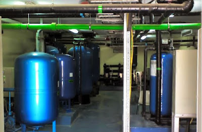
Water Treatment Plant Major Equipment
The extent of testing during erection should include, but not be limited to, the following.

Checking the accuracy and alignment of plant erection. The accuracy should comply with the relevant standards, the specification or the plant manufacturer’s requirements as may be applicable or where no requirements exist, to a standard to be agreed between the Engineer and the service provider.

Checking the alignment of rotating equipment is to the manufacturer’s requirements.
Non-destructive testing of site welds as required by the relevant standard and as detailed in the specification.

Sponsored:

Types of Test during Erection

The types of test should be carried out in site as per nature of works. Particular for this project the types will be as below:

Hydro-static Test

Hydro-static testing of pipe work systems at a pressure of 1.5 times the design pressure but not less than 4.5 bars for a period of working hours, or at such other conditions as may be required by the pipe work design code.
Hydro-static tests should be carried out on steam generating units in accordance with the boiler design code.
 

Air-Pressure Test

Air piping should be subjected to an air pressure test rather than a hydro-static test.

Vessel Test by Hydro-static

Site fabricated tanks and vessels should be subjected to hydro-static tests in accordance with the relevant standards.

Draining after Test

After the hydro-static test is carried out, the complete assembly should be drained and any non-drain-able sections should be injected with an oxygen-absorbent chemical and elements plugged.
 

Test for Site Fabricated Stuff

Pressure vessels and other parts including pipe work that is made up on site and is subject to pressure or vacuums under normal or abnormal working conditions, should be subjected to a site hydraulic test at approved pressures and for approved periods in accordance with the relevant standard. Where no appropriate standard exist the hydraulic test pressure should not be less than 1.5 times design pressure or at such pressure to be agreed by the Engineer.
 

Alternating Air Pressure Test

Should, in the opinion of the Service provider and with the agreement of the Engineer, an hydraulic test be impracticable due to excessive loading on foundations other than steel, an air pressure test may be employed in accordance with requirements set out in BS 5500.

Vacuum tests should be carried out at the maximum test vacuum obtainable and the condition maintained for a period of two hours with the system isolated. The Service provider should state in the Schedule of Guarantees the fall in vacuum anticipated during this period but the rate of all should not exceed that which would occur due to the designed air leakage rate being attained.

Sponsored:

Calibration checks on all instrumentation.

Tests to be demonstrate the correct functioning of the control loops, protective devices, interlocks and alarms.

To be flushing out of all pipe-work systems which have not been fully cleaned and sealed before shipping to site. Other tests as specified which have not been previously conducted.

Smart House Wiring Systems


How to wire your home smartly? Yes, Engineering Science and Technology teaching us to be smart everywhere in our life. So, before going to building a new home or remodeling your existing one; you must think about smart house-wiring like others smart gadget.

Smart house-wiring means not only how to wire cables for automation, but also to be think about different theories of automation wirings, popular and international or local house-wiring standard protocols etc.

The aim of this article to introduce our self with definition of smart wiring system and the most broadly accepted useful smart house-wiring techniques based on data communication & telephony system, Television & Media server system, Security & Closed circuit camera system, Alarms & Fire detection systems and hubing with many more upcoming technological smart gadgets.


What Smart Wiring Is?

If you guy is not an electrician, smart wiring means wiring having everything dealing with wiring; like- switching the lighting-heating-cooling stuff, phone-fax-computer, audio-video-TV cablings, security, Internet and home automation with future upgrading provisions, and so on.

Several people mistakenly confuse Smart Wiring for framework join. Smart Wiring is a system that engages the grouping of an extensive variety of sorts of wires used around the home into a single stage, which considers the joining of an extensive variety of smart-home structures and sensors all through your home, and the capacity to incorporate for future too. A Smart Wiring system joins wiring for lighting, security, web correspondences, security systems and hypermedia or home entertainment arrangement.

Sponsored:

What Can Smart Wiring Do?

Why smart wiring rather than a conventional wiring? What can smart wiring actually do?

Very shortly, we can say; a smart wiring can turns an ordinary house into a smart hose just creating various devices connection facility in your home around. You may desire to connect your stuff like-

ü Analogue/Digital or satellite TV (Television) sets;
ü POTS, PABX, Skype or VOIP telephone system;
ü CCTV, Door Bugs, Panic Button, Smoke & Fire Detector and all kind of Security systems;
ü Computer, Printer, File sharing Wireless devices, LAN, WAN and all others data transfer systems;
ü VGA, HDMI & all kind of Camera and Media services system, and so on.


Essential Guidelines For Smart Wiring
   

Do not believe electricity myth anytime,  working with electricity can be dangerous even causes of death for single slip, and be mind- electricity never give you second chance for your any mistake.

Important guidelines for smart house wing system is not a complete list, but some of essential tips are as below:

Design & Documentation:

1. Figure out which of the services portrayed in now and which in future.
2. Find the smart-wiring center point close to the focal point of the house,
3. Decide phone, TV, PC and security gadget areas. Run cabling from the gadget areas back to the smart-wiring center point.
Documentation is important all the time, there is no chance to underestimate anything. Keep mind and do the system flexible and easy to change or expand in the future.

Data Cable Selection System:

Smart-wiring systems are generally based around a mix of CAT6 information link and RG6 quad protected cajole links, with Security link for security gadgets. A few establishments may require fiber optic link which is generally 56.5/125 micron multimode fiber in a 4 fiber breakout style group.

Enclosure Layout System:

It is required that to keep the circuit breakers towards the bottom of the enclosure along with power supplies, and  cable termination towards the top, and leaving room for the equipment in the center.

Enclosure Selection:

It's critical to pick a right sized enclosure with enough room. The enclosure in area will be the center point of your wiring network, so you need to ensure enough free space.

Terminals Using System:

Terminal blocks are the best way to keep wiring well-ordered and organized. Consider using separators and label holders to identify track of which cable is which.
Terminal blocks should spare the difficult task of trying to cram several cables into one place with enough breathing space. To make any change quickly ensure the keeping cable installation overview.

Finger Ttrunking System:

Using finger trunking is important to continue wiring in organized way. Place this between every DIN rail and around the outside. There are essentially more wires that need to experience the outside trunking. So, trunking should be at least double the width of the trunking between the DIN rails.

Junction Boxes Selection:

It is a wise decision to install a deep junction box to fit any sizes switching devices.

Surge Protection System:

Surge protection system is very much important for smart wired house. Surge can be cause of shutdown the whole system in a house any time. So it is required to install a Whole-House Surge Suppressor to protect your electrical appliances and home entertainment products.

Load Segregation:

Automation and non-automation load should segregate to make your house wiring so mart. Potential noise can be off isolating non-automation load. Kitchen, Laundry and heating load may go in one phase.

Proper Neutral and Earthing System:

Proper grounding or earthing system is very much important for safety issue for life and property.

Sponsored:

What is Smart Wire?

Smart House Wiring System

Smart wire is a wire which offers some technical and financial benefit like low-loss, heat proven, smoke free and so on.

Feature of a smart wire is as below:

ü Sequential Foot/Meter Markings;
ü System Specific Print Legend;
ü Application Specific Print Legend;
ü Alphanumeric Coding System Designation;
ü Colors; &
ü Rip Cords.
So, modern smart wire should be look like smart too. Such as it ensure easier cable management and reduce time consume in identifying, measuring, labeling, cable sealing etc.

You may like the following pages