WAZIPOINT Engineering Science & Technology

Monday, July 11, 2022

Type Test on Complete Underground Power Cables


Here in this article, we would like to present a sample type test report on complete underground power cable:


Cable Type Test

Bending test in accordance with IEC 60840, clause 12.3.3

A cable sample of approximately 40 m was bent six times around a test cylinder with a maximum diameter of (25 x (d+D) +5%) at ambient temperature.

The results are stated in annex A. For a picture of the bending test, a reference is made to Annex G.

 Result: The test was completed successfully.


Partial discharge test at ambient temperature in accordance with IEC 60840, clause 12.3.4.


After the bending test and short duration test, the cable samples were examined for partial discharges in accordance with IEC 60885-3 at ambient temperature. The sensitivity of the measuring circuit was checked with a calibrator, and the noise level was < 2 PC. The voltage was first raised to and held to 133 kV (1, 75 Uo) for 10 s and then lowered to 114 kV (1, 5 Uo). At this voltage, the partial discharges were measured. For the results, reference is made to Annex A.

Result: No visual internal partial discharges were established.

Measurement of the dielectric loss angle in accordance with IEC 60840, clause 12.3.5


After the partial discharge measurement as mentioned under 2.1, the dielectric losses of the test installation were measured at Uo and a conductor temperature of at least 95 °C.  The results are stated in annex A. 

 Result: The test results met the requirements.


Sponsored:

Heating cycle voltage test in accordance with IEC 60840, clause 12.3.6

The test installation was subjected to a power frequency test of 152 kV (2 Uo), 60 Hz for at least 480 h. During this test, the test set-up was subjected to at least 20 heating cycles. Each heating cycle consisted of 8 h heating and 16 h of natural cooling. During the last 2 h of each heating period, the conductor reached a temperature of at least  95 C (5 C above the maximum rated temperature). For the data of the test, a reference is made to Annex A.
Result: The test installation passed the test successfully. 


Partial discharge test in the hot condition in accordance with IEC 60840, clause 12.3.4

After the heating cycle voltage test, the test the set-up was examined for partial discharges in accordance with IEC 60885-3 at a conductor temperature of at least 95 °C The test was carried out as described in 2.1. The results are stated in annex A.
 Result: The test results met the requirements.

Short duration power frequency withstand voltage test in accordance with Tranco specification


After the above-mentioned tests the test installation was subjected to a power frequency test of 275 kV (3,6 Uo), 60 Hz for at least 1 minute. The test was carried out while the test installation was at ambient temperature.
Result: No breakdown occurred.

Impulse withstand voltage test in accordance with IEC 60840,  clause 12.3.7


After the above-mentioned tests, the test set-up was tested with an impulse voltage while the conductor was heated to a temperature of at least 95 C (5 C above the maximum rated temperature). The test was carried out in accordance with IEC 60230 and IEC 60060. The sample was tested with ten positive and ten negative voltage impulses of 650 kV. The oscillograms of these tests are stated in annex B.
Result: No breakdown occurred. 


Power frequency voltage test for 15 minutes in accordance with  IEC 60840, clause 12.3.7

Upon completion of the impulse withstand voltage test, a voltage test was executed with an alternating voltage of 50 Hz. The test installation was tested with a voltage of at least 190 kV  (2,5 Uo) for 15 minutes in accordance with the specification. The test was carried out while the test installation was at ambient temperature.
  Result: No breakdown occurred.

Examination of the cable and the accessories after the tests in accordance with IEC 60840, clause 12.3.8

After completion of the electrical tests as mentioned above the cable and the accessories were dismantled and inspected for electrical degradation of the insulation. For pictures of the dismantling, a reference is made to Annex I.

 Result: No signs of electrical degradation were detected. The construction of the accessories complied with the construction drawing


Tests on semi-conducting layers

Electrical resistivity before and after aging in accordance with IEC 60840, clause 12.3.9


The resistivity of the extruded semi-conducting layers was measured and calculated according to annex B of the IEC 60840. The aging treatments were carried out in accordance with IEC 60811-1-2, clause 8 at a temperature of 100 C for 7 x 24 h. The measurement was carried out at a temperature of 90 C. The test results are stated in annex F.

Result: The test results met the requirements as stated in the specification

Thursday, July 7, 2022

Electric Actuator RA-300 User Manual and Specification

Specification and User Manual for Electric Actuator R-300


The RA-3000 series synchronous motor-driven reversible actuators are generally available for 3-point (floating) or with electric positioned for 0…10 V control.

You will get feature factory-calibrated pressure switches to provide specified close-off ratings.

The RA-3000 series actuators are available in three sizes 1600 N, 1800 N, and with 3000 N nominal force and can be used with JC-fanged valves according to the maximum close-off pressure ratings specified.

Saturday, June 25, 2022

Regulation of a Transformer is Helpful for Systems?

 What is the Regulation of a Transformer?

The regulation of the transformer menses the voltage regulation of a transformer.
 
So, the voltage regulation of a transformer may define as a transformer voltage regulation is the percentage change of the output voltage from no-load to full-load. 

Please remember that since the power factor is a determining factor in the secondary voltage, so power factor influences the voltage regulation of the transformer. 

Monday, June 13, 2022

Autotransformer Specialty Difference from Conventional Transformer


Auto Transformer

What is an autotransformer?

Auto Transformer is not any automatic machine or equipment. Actually, the word auto adds before the Transformer because the autotransformer is single core transformer rather than conventional two cores.

Transformer Introduction and FAQ: Frequently Asked Question of a Transformer


Transformer Introduction and FAQ
Major Parts of an Electrical Transformer

FAQ of an Electrical Transformer


Introduction of a Transformer

A transformer is a static electrical machine used to change the voltage of alternating current that has the same frequency. Before going to details on the electric transformer, types of transformers,  parts of transformer, construction of a transformer, step-up transformer, voltage transformer, current transformer and transformer equation, we would like to understand-

Saturday, June 11, 2022

Skin Effect of Electrical Power Transmission Line


What is Skin Effect of Power Lines?

The tendency of the alternating current to concentrate near the surface of the conductor is called the skin effect. The direct current distribution in a conductor is the same. But the alternating current distribution in a conductor is not uniform. The current density near the surface is higher than near the center of the conductor which means that the current flow in the surface of the conductor is greater than the current flow in the center of the conductor. It is influenced by the frequency of current. If the current frequency is high then the current distribution is more non-uniform. This effect is called the skin effect. The effective cross sectional area of ​​the conductor through which the current flows is reduced.

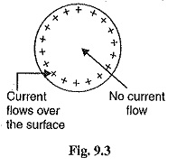
Skin effect on power lines – If the conductor carries a steady direct current (dc), this current is evenly distributed across the X-section of the conductor. However, the alternating current flowing through the conductor is not evenly distributed, and tends to concentrate near the conductor surface as shown in Figure 9.3. This is known as the epidermal effect.

The tendency of alternating current to concentrate near the surface of a conductor is known as the skin effect.

The skin effect of power lines reduces the effective cross-sectional area of ​​a conductor that carries current. As a result, the resistance of the conductor increases slightly when carrying an alternating current. The cause of the skin effect on power lines can be easily explained. A solid conductor can be thought of as a number of strands, each carrying a small portion of the electrical current. The inductance of each strand depends on its location. Therefore, the strands near the center are surrounded by a larger magnetic flux and thus have a greater inductance than the one near the surface. Due to the high reactance of the internal strands, an alternating current flows near the conductor surface. This current crowding near the conductor surface is a skin effect on the transmission line.

Skin Effect of Electrical Power Transmission Line
Skin effect of power line

The skin effect of power lines depends on the following factors:

1. Material properties
2. Wire diameter-increases with wire diameter.
3.Frequency – increases with increasing frequency.
4. Wire shape-twisted wire is less than solid wire.

Note that the skin effect of the transmission line is negligible at low supply frequencies (<50 Hz) and small conductor diameters (<1 cm).

Skin Affecting Factors

  • Frequency - The skin effect increases as the frequency increases;
  • Diameter - It increases with increase in diameter of conductor;
  • Conductor size - The skin effect is greater in solid conductors and less in trapped conductors because the surface area of ​​solid conductors is higher;
  • Material Type - The effect of the skin increases with an increase in the permeability of the material (permeability is the ability of the material to support the formation of a magnetic field).

Material effect on skin depth

  • In a good conductor, skin depth varies as the inverse square root of the conductivity. This means that better conductors have a reduced skin depth;
  • The overall resistance of the better conductor remains lower even with the reduced skin depth;
  • Skin depth also varies as the inverse square root of the permeability of the conductor. In the case of iron, its conductivity is about 1/7 that of copper;
  • In case of ferromagnetic its permeability is about 10,000 times greater. This reduces the skin depth for iron to about 1/38 that of copper, about 220 micrometres at 60 Hz;
  • Iron wire is thus useless for A.C. power lines. The skin effect also reduces the effective thickness of laminations in power transformers, increasing their losses;
  • Iron rods work well for (DC) welding but it is impossible to use them at frequencies much higher than 60 Hz.


How to reduce the effect of skin:

  1. ACSR bundle conductors are used to minimize skin effects. ACSR conductors are steel that are placed inside the center or center of the conductor and aluminum conductors are positioned around the steel wire. Steel increased the conductor strength but reduced the surface area of ​​the conductor. Thus, current flows in the outer layer of the conductor and no current flows in the center of the conductor. Thus, reducing the proximity effect on the conductor.
  2. Use cable material with low magnetic permeability. (This minimizes the effect, but usually comes at the cost of high basic resistance per unit length, so this can be fine if the lines are short.)
  3. Reduce the size of the conductor.
  4. Increasing the voltage by reducing the current reducing the effect of the skin in the same conductor.

Mitigation of Skin Effect

• Instead of normal conductors/wires A type of cable called litz wire (from the German Litzendraht, braided wire) is used to mitigate the skin effect for frequencies of a few kilohertz to about one megahertz.

• It consists of a number of insulated wire strands woven together in a carefully designed pattern, so that the overall magnetic field acts equally on all the wires and causes the total current to be distributed equally among them.

• With the skin effect having little effect on each of the thin strands, the bundle does not suffer the same increase in AC resistance that a solid conductor of the same cross-sectional area would due to the skin effect.


You may like the following pages