WAZIPOINT Engineering Science & Technology: November 2018

Thursday, November 22, 2018

JACK AND PLUG CONFIGURATION IN DIFFERENT COUNTRIES

Jack & Plug or Plug & Socket Configuration in Various Countries

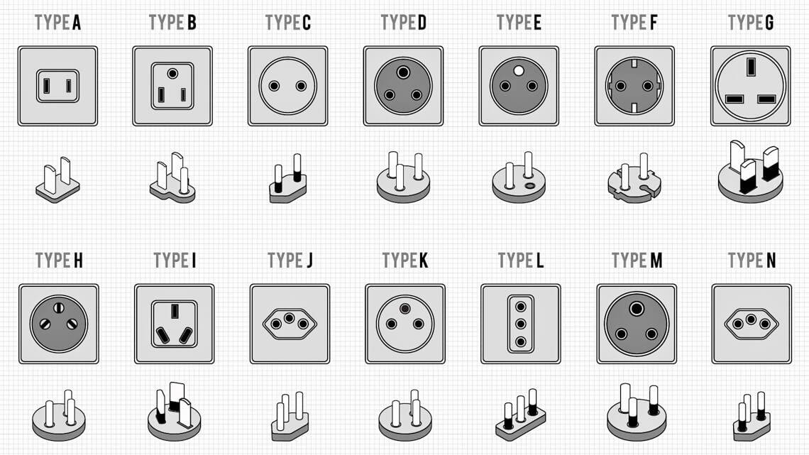
Fig-Plug and Socket Types


There is no guy who hasn’t faced fixing unmatched Plug & Socket or Jack & Plug ever you say. Especially you, who frequently visit the different location or live in an Asian country where not follow any specific standard, often face this problem during using computer/laptop, mobile etc charger.

Most of the developed countries use jack and plug configuration as per some international standard or their local standard, but many countries do not follow any specific standard, they use various configurated jack and plugs which causes this problem.

Some of the standard jack and plug descriptions are quoted below that are used in Europe, America and other countries-


  Jack                   Plug
Description
Using Countries
Schuko European CEE 7 Jack & Plug
Schuko European
CEE 7
EU, Austria, Netherland, French, Germany, Irish, Italy, Norway, Sweden, Switzerland
Ungrounded Eurocord CEE 7/16 Jack & Plug

Ungrounded Eurocord
CEE 7/16
EU, Belgium, Denmark, Netherland, French, Germany, Italy, Norway, Portugal, Spain, Sweden, Switzerland, UK, Singapore
Belgium/ French Socket CEE 7/7 Jack & Plug
Belgium/ French Socket
CEE 7/7
Belgium, French
British Standard BS 1363 Jack & Plug
British Standard
BS 1363
French, Irish, UK, Singapore
Old British Standard BS 546 Jack & Plug
Old British Standard
BS 546
Portugal, Spain
North American Ungrounded Jack & Plug North American Ungrounded Mexico, Canada
North American NEMA 5-15 Jack & Plug North American
NEMA 5-15
Canada
Australian Standard AS/NZS 3312 Jack & Plug Australian Standard
AS/NZS 3312
Australia
Typical Pipe Work In a Project
Japanese Standard JIS C 8303  Jack & Plug
Japanese Standard
JIS C 8303
Japan
Ads wazipoint          
Get Free 

Most Using Standard in Electrical Engineering 

Sponsored:


NFPA - National Fire Protection Association - National code that covers anything to do with flammable stuff (electrical, dust, combustibles, sprinklers, fire alarms, etc);


NEC - National Electric Code, NFPA 70 (NEC is a section of the NFPA code) - Addresses proper installation of electrical equipment, devices and wiring.

The first NEC document was written in 1897 at the insistence of various insurance, electrical, architectural and other interested parties. Up to and including 2008, there have been a total of 51 editions. It is revised on a regular three-year schedule. The National Electrical Code is divided into approximately 120 articles;


NEMA - National Electric Manufacturers Association- the trade organization for electrical manufacturers. Sets common rules, practices and certifications for the manufacture of electrical components and devices;


IEC - International Electric Code - International version of NEMA,
IEC set requirements that cover the installation and management of electronic systems along with wiring and electric shock protection.


Quiz: Here is a Jack & Plug quiz for the readers; We everybody have seen the three pin Jack & Plug, if you look at this three pin plug again, there are two pin for phase and neutral are same size, and one pin for earthing or grounding which is thicker and bigger than others.
 Sponsored:


Question for you, why this earthing pin is thicker and bigger than others? 
You can give your answer in the comments below.

Tuesday, November 6, 2018

Motor and Pump Application Formula Save Energy and Make You Smart Designer


How Motor and Pump Application Formula can Save Energy and Make You Smart Designer?

Motor and Pump applications simple formula can save energy by helping effective design for using maximum efficiency of your equipment. 


Some times we ignore these basic design formula and use larger size of equipment using thump-role formula which cases extra money energy as wastage. 


A gerotor
A gerotor (image does not show intake or exhaust) (Photo credit: Wikipedia)
If we love ourself to be a energy saver or go to as green environment; we should take care of every bit of energy uses. Following motor and pump applications formula can help us to effective use of energy.

Centrifugal Applications


AFFINITY LAWS

The Affinity Laws of centrifugal pumps or fans indicates the influence on volume capacity, head (pressure) and/or power consumption of a pump or fan due to


  • change in speed of wheel - revolutions per minute (rpm)
  • geometrically similarity - change in impeller diameter
Following three affinity formulas are related with simply motor horse powerRPM (revolution per minute), Flow and pressure.

Flow2
=
RPM2
Flow1
RPM1
Pres2
=
(RPM2)2
Pres1
(RPM1)2
HP2
=
(RPM2)3
HP1
(RPM1)3


Where:
Pres=Pressure
RPM= Revolutions Per Minute

FANS AND BLOWERS


Centrifugal Fans and Blowers typically have one of seven types of wheels that draw the air into the inlet of the blower housing, through the wheel, and discharges it at 90 degrees out through the discharge of the housing.

The two most common types of Centrifugal Blowers are Pressure Blowers and Volume Blowers.

Fans and Blowers are very common uses in industry, Basic three formula can help you to design effective and perfect size of fan and blower as your desired. 

HP  =
CFM x PSF
33000 x Efficiency of Fan
HP  =
CFM x PIW
6356 x Efficiency of Fan


HP  =
CFM x PSI
229 x Efficiency of Fan


Where:
CFM= Cubic Feet per Minute
PIW= Inches of Water Gauge
PSF= Pound per Square Foot
PSI= Pound per Square Inches

PUMPS

Pump is a device that moves fluids (liquids or gases), or sometimes slurries, by mechanical action. Pumps can be classified into three major groups according to the method they use to move the fluid: direct lift, displacement, and gravity pumps.

Perfect capacity of pump design and operation is very important which can help the following two simple formula.


HP  =
GPM x FT x Specific Gravity
3960 x Efficiency of Pump


HP  =
GPM x PSI x Specific Gravity
1713 x Efficiency of Pump


Where:
FT= Head in Feet
GPM= Gallons Per Minute
PSI= Pounds Per Square Inch

VOLUME OF LIQUID IN A TANK


Gallons= 5.875 x D2 x H
1 gallon (US) of water weights 8.33 lb
Specific gravity of water- 1.0

Where:
D= Diameter of Tank in feet
H= Height of liquid in feet

Motor Application Formulas

Following motor applications formula is necessary everyday every moment.  It will help to calculate your motor's HP (Horse Power), Kilowatts, Torque in Pound-feet or Newton-meter.

HP(Horse Power)  =
Torque (lb-ft) x RPM
5252


Kilowatts  =
Torque (N-m) x RPM
9550


Torque (lb-ft)  =
Horse Power (HP) x 5252
RPM


Torque (N-m) =
Kilowatts x 9550
RPM


1HP= 746 watts
Hope motor and pump application formula will help to design a smart and effective energy saving initiative. 

Sunday, November 4, 2018

Manufacture Of Electric Power Cables and Chronological Development

Underground Power Cable Installation


This Video Clip shows how installed underground power cable. 
This is not used modern equipment and technology.

You could see the initial technology for oilfield underground power cable and it's installation and erection procedure. 


Early to Latest Technology for Power Cable Manufacturing:

The telegraph line was the earliest device where people first think and establish to transmit electrical energy through underground cable.

Mr. Bruce S. Bernstein & William A. Thue quoted in the book of Historical Perspective of Electrical Cables as-
In 1812, Baron Schilling detonated a mine under the Neva River at St. Petersburg, Russia, by using an electrical pulse sent through a cable insulated with strips of India rubber. This is probably the earliest use of a continuously insulated conductor on record.  One of the earliest experiments with an underground cable was made by Francis Ronalds in 1816. This work was in conjunction with a system of telegraphy consisting of 500 feet of bare copper conductor drawn into glass tubes, joined together with sleeve joints and sealed with wax. The tubes were placed in a creosoted wooden trough buried in the ground. Ronalds was very enthusiastic over the success of this line, predicting that underground conductors would be widely used for electrical purposes and outlining many of the essential characteristics of a modern distribution system. 
Yes, 200 years earlier Mr. Ronalds was excited to be success on his idea; now today we are getting hi-tech cable manufacturing facilities, salute Mr. Ronalds’s dreams!  


Chronological Development of Cable System:

Sponsored:


In 1837, W.R. Cooke and Charles Wheatstone laid an underground line along the railroad right-of-way between London’s Euston and Camden stations in London for telegraphy.

In 1842, S.F.B. Morse laid a cable insulated with jute, saturated in pitch, and covered with strips of India rubber between Governor’s Island and Castle Garden in New York harbor.

In 1842, Gutta-percha was introduced into Europe by Dr. W.Montgomery, and in 1846 was adopted on the recommendation of Dr. Werner Siemens for the telegraph line.

In 1860, vulcanized rubber was used for the first time as insulation for wires.

In 1882, of L. Gaulard and J.D. Gibbs who designed a crude alternating current system using induction coils as transformers.

In 1885, alternating current system was introduced into the United States by George Westinghouse.

In early 1886 an experimental installation went in service at Great Barrington, Massachusetts, (about 1,000V/200V).

In 1890, the first important line (10,000 volts) insulated with paper was installed by Ferranti in between Deptford and London.

In 1900 and after, start universal use of wood pulp paper in cables.

In 1914, introduction of the shielded design of multiple conductor cables by Martin Hochstadter.

In1925, the impregnating compound was changed from a rosin-based compound to a pure mineral oil circa.

In 1927, the patent by H.W.Fisher and R.W.Atkinson revealed that the dielectric strength of impregnated paper-insulated cable could be greatly increased by maintaining it under pressure.
In 1941, the polyethylene developed.

In 1947, PE was furnished cable insulation as 15 kV.

In the mid 1970s, a grade of tree-retardant polyethylene (TR-HMWPE) was introduced.

In 1975, extruded dielectric cables began.

In 1980, Jackets became increasingly popular,

In1980, EPR cables became more popular.

In 1981, the introduced of “dry cure” cables.

In 1982, the introduction of tree-resistant cross-linked polyethylene (TR-XLPE).

In 1983, the polybutene replaced the impregnating compound oil circa.

In 1984, the market was approximately 65 percent XLPE, 25 percent TR-XLPE and 10 percent EPR.
In 1995, the market was approximately 45 percent TRXLPE, 35 percent XLPE, and 20 percent EPR

Latest Technology is Using to Manufacture Power Cable: 

Sponsored:


Nowadays cables are verity sizes and types for different uses which can carry up to 500 kilovolts. For power transmission from generation station to user end high voltage power cables are used, on the other hand low voltage or flexible power cables are used everyday life. Some special type cables are used for special purposes such as mineral insulated cables for burning protection, enamelled wires for motor/transformer winding, tinsel wires for telephone handset, cooker cables for asbestos insulation and so on.


Copper and  Aluminium are mainly used to power cable manufacture due to conductivity and economic prices. Many insulation materials have been used on different types of cables. The most common types are plastic materials, such as PVC, XLPE and EPR

Today, the technology needed to ensure an electrical cable stays in good working condition for long time without problems involves complicated manufacturing processes which require highly qualified man and machineries.

You may like the following pages